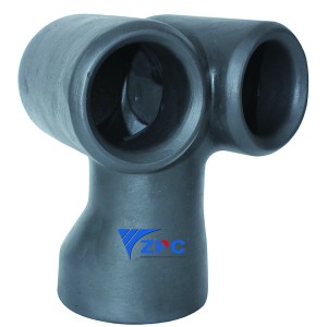
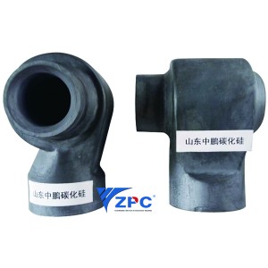
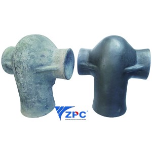
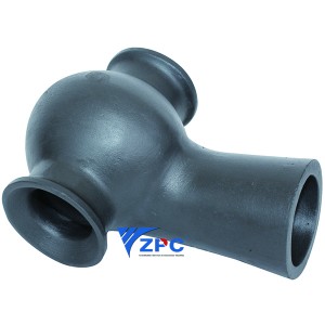
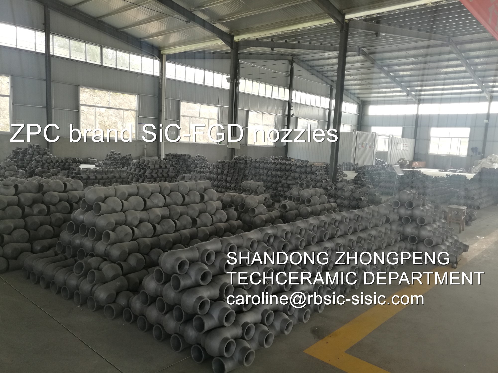
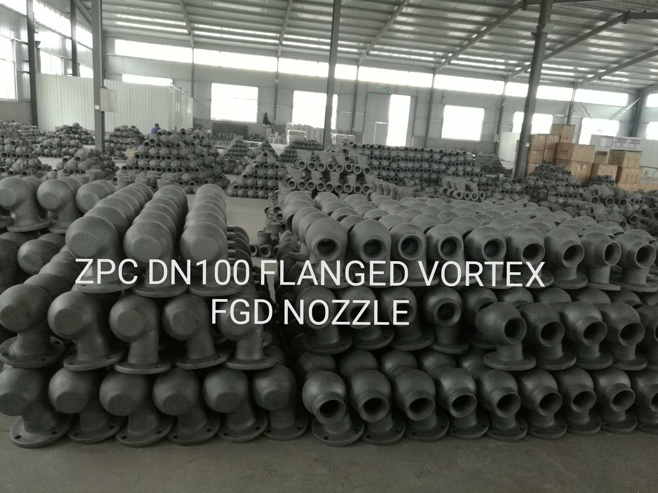
Silicon Carbide FGD Nozzle for desulfurization in power plant
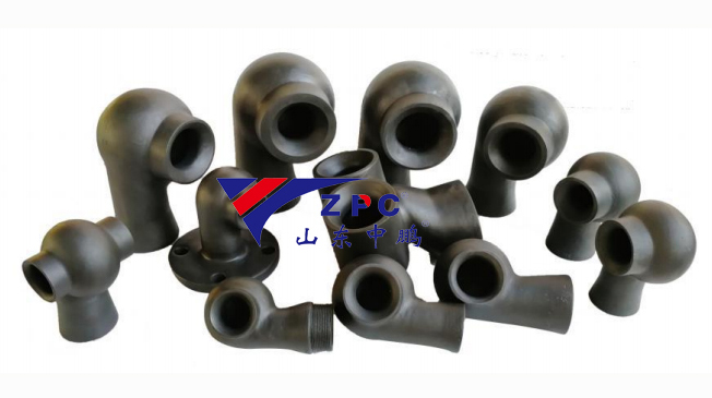
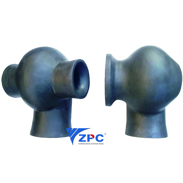
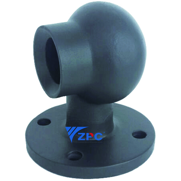
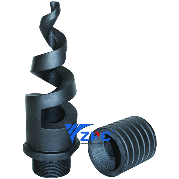
Flue Gas Desulfurization (FGD) Absorber Nozzles
Removal of sulfur oxides, commonly referred to as SOx, from an exhaust gases using an alkali reagent, such as a wet limestone slurry.
When fossil fuels are utilized in combustion processes to run boilers, furnaces, or other equipment they have the potential to release SO2 or SO3 as part of the exhaust gas. These sulfur oxides react easily with other elements to form harmful compound such as sulfuric acid and have the potential to negatively affect human health and the environment. Due to these potential effects, control of this compound in flue gases is an essential part of coal fired power plants and other industrial applications.
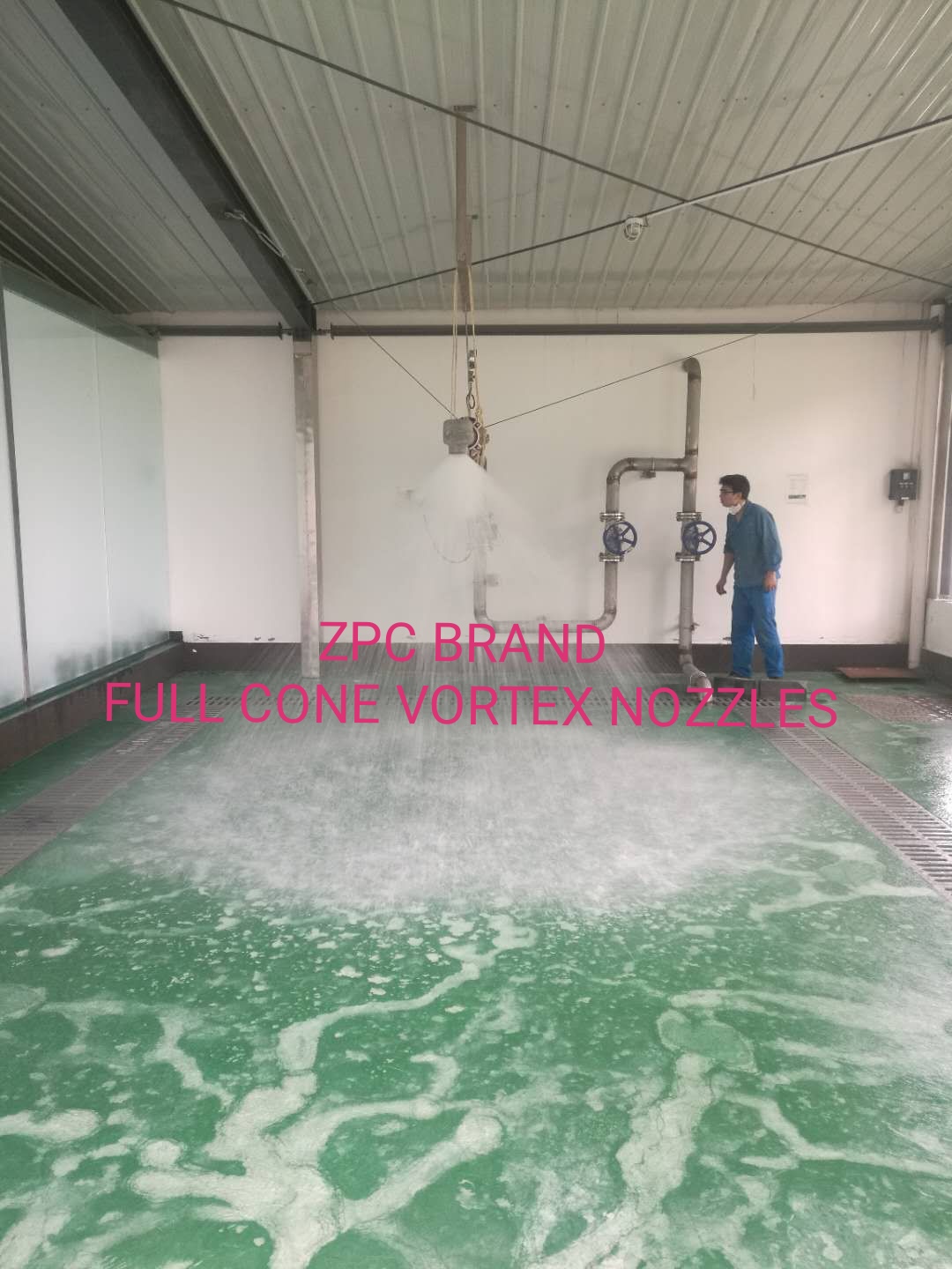
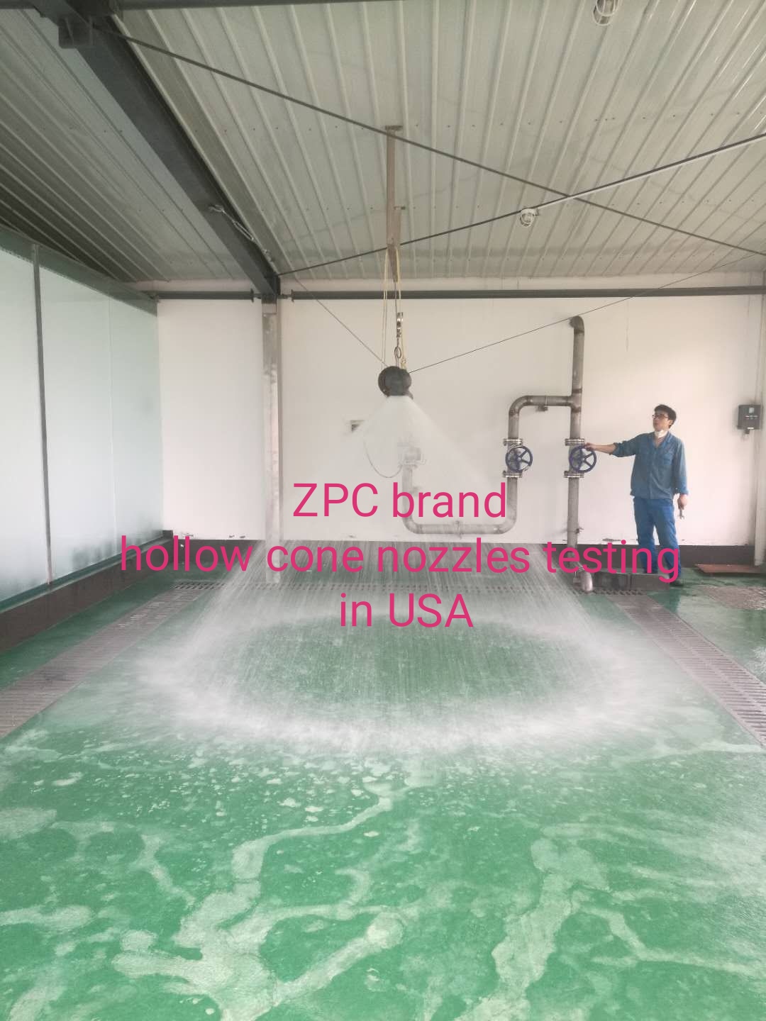
Due to erosion, plugging, and build-up concerns, one of the most reliable systems to control these emissions is an open-tower wet flue gas desulfurization (FGD) process using a limestone, hydrated lime, seawater, or other alkaline solution. Spray nozzles are able to effectively and reliably distribute these slurries into absorption towers. By creating uniform patterns of properly sized droplets, these nozzles are able to effectively create the surface area needed for proper absorbtion while minimizing entrainment of the scrubbing solution into the flue gas.
Selecting an FGD Absorber Nozzle:
Important factors to consider:
Scrubbing media density and viscosity
Required droplet size
The correct droplet size is essential to ensuring proper absorption rates
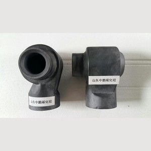
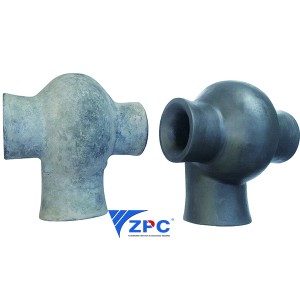
Nozzle material
As the flue gas is often corrosive and the scrubbing fluid is frequently a slurry with high solids content and abrasive properties, selecting the appropriate corrosion and wear resistant material is important
Nozzle clog resistance
As the scrubbing fluid is frequently a slurry with high solids content, selection of the nozzle with regard to clog resistance is important
Nozzle spray pattern and placement
In order to ensure proper absorption complete coverage of the gas stream with no bypass and sufficient residence time is important
Nozzle connection size and type
Required scrubbing fluid flow rates
Available pressure drop (∆P) across the nozzle
∆P = supply pressure at nozzle inlet – process pressure outside nozzle
Our experienced engineers can help determine which nozzle will perform as required with your design details
Common FGD Absorber Nozzle Uses and Industries:
Coal and other fossil fuel power plants
Petroleum refineries
Municipal waste incinerators
Cement kilns
Metal smelters
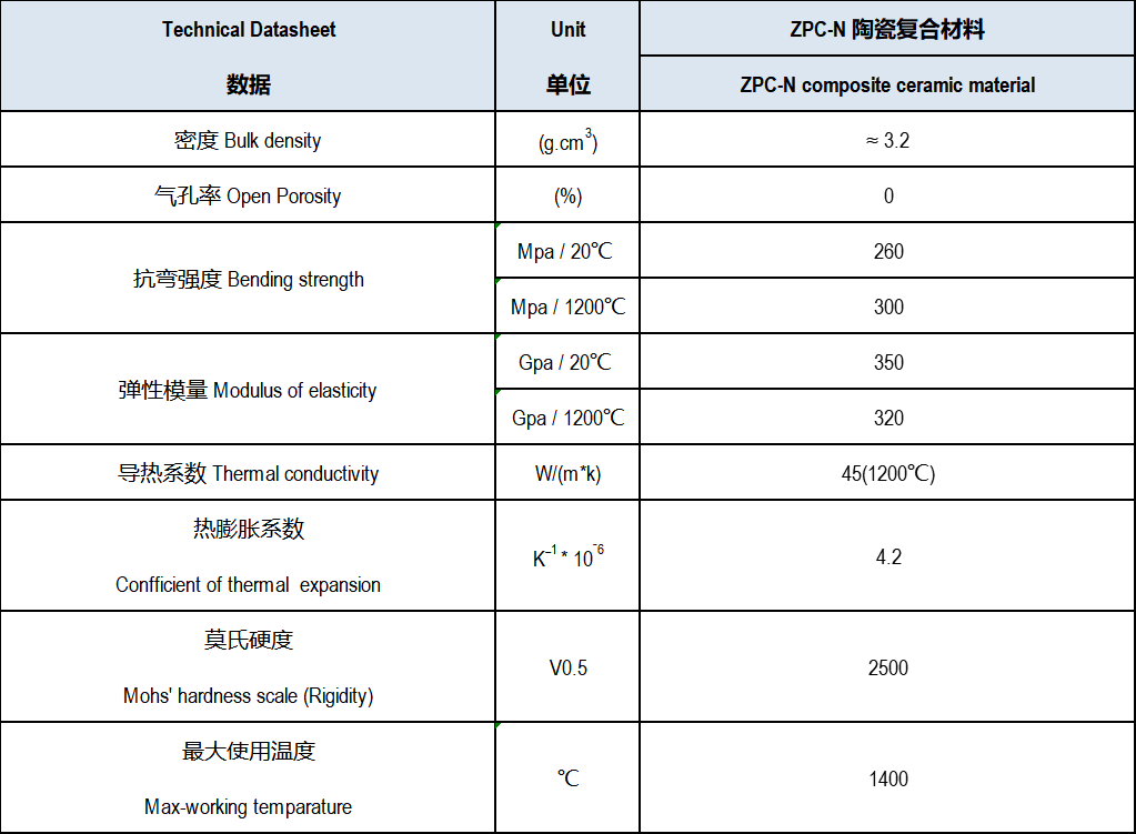
SiC Material Datasheet
Drawbacks with Lime/Limestone
As shown in Figure 1, FGD systems employing lime/limestone forced oxidation (LSFO) include three major sub-systems:
- Reagent preparation, handling and storage
- Absorber vessel
- Waste and byproduct handling
Reagent preparation consists of conveying crushed limestone (CaCO3) from a storage silo to an agitated feed tank. The resulting limestone slurry is then pumped to the absorber vessel along with the boiler flue gas and oxidizing air. Spray nozzles deliver fine droplets of reagent that then flow countercurrent to the incoming flue gas. The SO2 in the flue gas reacts with the calcium-rich reagent to form calcium sulfite (CaSO3) and CO2. The air introduced into the absorber promotes oxidation of CaSO3 to CaSO4 (dihydrate form).
The basic LSFO reactions are:
CaCO3 + SO2 → CaSO3 + CO2 · 2H2O
The oxidized slurry collects in the bottom of the absorber and is subsequently recycled along with fresh reagent back to the spray nozzle headers. A portion of the recycle stream is withdrawn to the waste/byproduct handling system, which typically consists of hydrocyclones, drum or belt filters, and an agitated wastewater/liquor holding tank. Wastewater from the holding tank is recycled back to the limestone reagent feed tank or to a hydrocyclone where the overflow is removed as effluent.
| Typical Lime/Limestone Forced Oxidatin Wet Scrubbing Process Schematic |
 |
Wet LSFO systems typically can achieve SO2 removal efficiencies of 95-97 percent. Reaching levels above 97.5 percent to meet emissions control requirements, however, is difficult, especially for plants using high-sulfur coals. Magnesium catalysts can be added or the limestone can be calcined to higher reactivity lime (CaO), but such modifications involve additional plant equipment and the associated labor and power costs. For example, calcining to lime requires the installation of a separate lime kiln. Also, lime is readily precipitated and this increases the potential for scale deposit formation in the scrubber.
The cost of calcination with a lime kiln can be reduced by directly injecting limestone into the boiler furnace. In this approach, lime generated in the boiler is carried with the flue gas into the scrubber. Possible problems include boiler fouling, interference with heat transfer, and lime inactivation due to overburning in the boiler. Moreover, the lime reduces the flow temperature of molten ash in coal-fired boilers, resulting in solid deposits that would otherwise not occur.
Liquid waste from the LSFO process is typically directed to stabilization ponds along with liquid waste from elsewhere in the power plant. The wet FGD liquid effluent can be saturated with sulfite and sulfate compounds and environmental considerations typically limit its release to rivers, streams or other watercourses. Also, recycling wastewater/liquor back to the scrubber can lead to the buildup of dissolved sodium, potassium, calcium, magnesium or chloride salts. These species can eventually crystallize unless sufficient bleed is provided to keep the dissolved salt concentrations below saturation. An additional problem is the slow settling rate of waste solids, which results in the need for large, high-volume stabilization ponds. In typical conditions, the settled layer in a stabilization pond can contain 50 percent or more liquid phase even after several months of storage.
The calcium sulfate recovered from the absorber recycle slurry can be high in unreacted limestone and calcium sulfite ash. These contaminants can prevent the calcium sulfate from being sold as synthetic gypsum for use in wallboard, plaster, and cement production. Unreacted limestone is the predominant impurity found in synthetic gypsum and it is also a common impurity in natural (mined) gypsum. While limestone itself does not interfere with the properties of wallboard end products, its abrasive properties present wear issues for processing equipment. Calcium sulfite is an unwanted impurity in any gypsum as its fine particle size poses scaling problems and other processing problems such as cake washing and dewatering.
If the solids generated in the LSFO process are not commercially marketable as synthetic gypsum, this poses a sizeable waste disposal problem. For a 1000 MW boiler firing 1 percent sulfur coal, the amount of gypsum is approximately 550 tons (short)/day. For the same plant firing 2 percent sulfur coal, the gypsum production increases to approximately 1100 tons/day. Adding some 1000 tons/day for fly ash production, this brings the total solid waste tonnage to about 1550 tons/day for the 1 percent sulfur coal case and 2100 tons/day for the 2 percent sulfur case.
EADS Advantages
A proven technology alternative to LSFO scrubbing replaces limestone with ammonia as the reagent for SO2 removal. The solid reagent milling, storage, handling and transport components in an LSFO system are replaced by simple storage tanks for aqueous or anhydrous ammonia. Figure 2 shows a flow schematic for the EADS system provided by JET Inc.
Ammonia, flue gas, oxidizing air and process water enter an absorber containing multiple levels of spray nozzles. The nozzles generate fine droplets of ammonia-containing reagent to ensure intimate contact of reagent with incoming flue gas according to the following reactions:
(1) SO2 + 2NH3 + H2O → (NH4)2SO3
(2) (NH4)2SO3 + ½O2 → (NH4)2SO4
The SO2 in the flue gas stream reacts with ammonia in the upper half of the vessel to produce ammonium sulfite. The bottom of the absorber vessel serves as an oxidation tank where air oxidizes the ammonium sulfite to ammonium sulfate. The resulting ammonium sulfate solution is pumped back to the spray nozzle headers at multiple levels in the absorber. Prior to the scrubbed flue gas exiting the top of the absorber, it passes through a demister that coalesces any entrained liquid droplets and captures fine particulates.
The ammonia reaction with SO2 and the sulfite oxidation to sulfate achieves a high reagent utilization rate. Four pounds of ammonium sulfate are produced for every pound of ammonia consumed.
As with the LSFO process, a portion of the reagent/product recycle stream can be withdrawn to produce a commercial byproduct. In the EADS system, the takeoff product solution is pumped to a solids recovery system consisting of a hydrocyclone and centrifuge to concentrate the ammonium sulfate product prior to drying and packaging. All liquids (hydrocyclone overflow and centrifuge centrate) are directed back to a slurry tank and then re-introduced into the absorber ammonium sulfate recycle stream.

- EADS systems provide higher SO2 removal efficiencies (>99%), which gives coal-fired power plants more flexibility to blend cheaper, higher sulfur coals.
- Whereas LSFO systems create 0.7 tons of CO2 for every ton of SO2 removed, the EADS process produces no CO2.
- Because lime and limestone are less reactive compared to ammonia for SO2 removal, higher process water consumption and pumping energy is required to achieve high circulation rates. This results in higher operating costs for LSFO systems.
- Capital costs for EADS systems are similar to those for constructing an LSFO system. As noted above, while the EADS system requires ammonium sulfate byproduct processing and packaging equipment, the reagent preparation facilities associated with LSFO are not required for milling, handling and transport.
The most distinctive advantage of EADS is the elimination of both liquid and solid wastes. The EADS technology is a zero-liquid-discharge process, which means no wastewater treatment is required. The solid ammonium sulfate byproduct is readily marketable; ammonia sulfate is the most utilized fertilizer and fertilizer component in the world, with worldwide market growth expected through 2030. In addition, while the manufacturing of ammonium sulfate requires a centrifuge, dryer, conveyer and packaging equipment, these items are non-proprietary and commercially available. Depending on economic and market conditions, the ammonium sulfate fertilizer can offset the costs for ammonia-based flue gas desulfurization and potentially provide a substantial profit.
| Efficient Ammonia Desulfurization Process Schematic |
 |
Shandong Zhongpeng Special Ceramics Co., Ltd is one of the largest silicon carbide ceramic new material solutions in China. SiC technical ceramic: Moh’s hardness is 9 (New Moh’s hardness is 13), with excellent resistance to erosion and corrosion, excellent abrasion – resistance and anti-oxidation. SiC product’s service life is 4 to 5 times longer than 92% alumina material. The MOR of RBSiC is 5 to 7 times that of SNBSC, it can be used for more complex shapes. The quotation process is quick, the delivery is as promised and the quality is second to none. We always persist in challenging our goals and give our hearts back to society.